What is Automatic Generator Start (AGS)?
We chose to install the Magnum MEAGSS Automatic Generator Start Controller so that we could have our Onan onboard generator start automatically when the temperature reached a certain level, or if the battery dropped below a specific voltage.
Use Case(s):
- Camping primarily in Florida with a dog, and especially during the summer time when everyone is taxing the campgrounds power system, if the power goes out, the generator would kick on the keep the air going and keep our dog, Leo, safe.
- For the most part, we weekend warrior our camping trips. This means turning the fridge on Wednesday or Thursday night in our storage lot to cool down, ahead of loading up on Friday and rolling out. On occasion, we have left an LED light on in the pantry causing the battery to run dead, and our fridge not to be cold. The AGS will turn on the generator if this happens now, making sure the fridge cools down in time.
Installation
The install was pretty simple. On a scale of 1 to 10, if you have basic 12v electrical knowledge its a 2-3.
WARNING: these instructions are for illustrative purposes only. They do not replace the install instructions that come with the AGS, and you take full responsibility if you shock yourself or blow up your generator/camper.
Parts/Tools Needed*
- Magnum MEAGSS Automatic Generator Start Controller – https://amzn.to/2XbH5ts
- Closed End Crimp Connectors – https://amzn.to/3ix2fu8
- Multimeter – https://amzn.to/3ix2PrO
- Wire Cutters – https://amzn.to/3Aspuvz
- In line fuse holders w/ 5a Fuses – https://amzn.to/2Uh7W6g
- Wire Crimpers – I use a cheap pair from Harbor Freight
- Drill/Screwdriver (cross-tip)
- 16 ga. wire (different colors if you want)
*Note: As an Amazon Associate I earn from qualifying purchases.
Set Internal Controller Settings
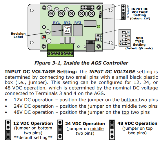
NOTE: Prior to mounting controller, remove the cover, and set the internal dip switches to the correct setting
- Remove the 4 screws securing the cover of the Controller using a cross-tip screwdriver
- Gently remove and retain the Controller Cover
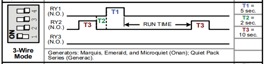
- For my Grand Design 31g with the onboard Onan generator, I selected the 3-Wire Mode by toggling Switch 1 to ON
NOTE: The controller did not come with a wire jumper, but 12V is the default without a jumper. If you have done anything to change your system from 12v, then you may need to go to your local hardware store and procure a jumper to select the correct setting.
Choose Mounting Location
You’re going to want to mount the AGS Controller somewhere close to your control panel and remote generator start panel, as you’ll be tapping into the wires from those panels to properly connect the AGS Controller.
We chose the cabinet above our TV.
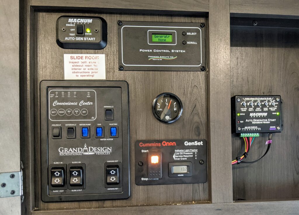
- We mounted the remote start button above the Convenience Center and to the left of the Power Control System.
- We mounted the AGS Controller in the adjacent cabinet
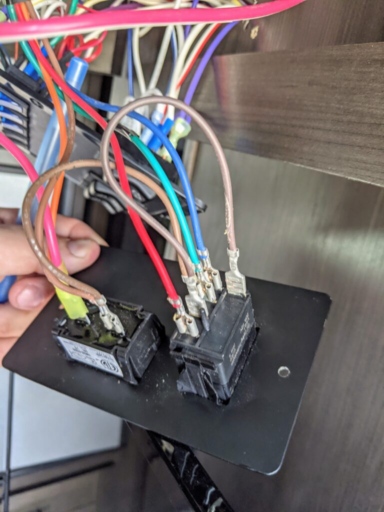
Remote Start Button Mounting
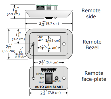
- Separate the Remote Start Face-Plate from Remote Bezel
- Use the backing plate to trace the opening (we used a sharpie)
- Use a razor knife to cut the opening
- Test fit the Remote Start module with the remote cable plugged in to it (I found you had to have the hole a little larger than the template to account for the cable being connected
- Secure backing plate and Face-Plate with provided screws
NOTE: when mounting the Remote Start Button – there is a ton of extra wire, I looped it up and zip tied it, and then shoved it in to the upper left corner of my opening, as to not interfere with getting the Convenience Panel back in.
Mount AGS Controller
- We mounted the Control Panel in the adjacent cabinet from the Convenience Center
- Mount Controller by using 4 screws provided and an Electric Drill
- Drill a 3/4″ hole, using a spade bit to allow wires to be run between the cabinets
Remove the Convenience Center Panel
- Remove the Convenience Center by pulling back gently on the black plastic trim panel from the edges
- Remove the screws securing the Convenience Center
- Pull the panel forward gently (there are a lot of wires back there)
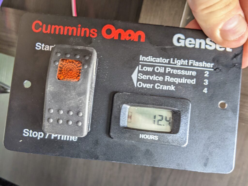
Remove the Cummins Onan Start Panel
- Remove the two (2) screws securing the Cummins Onan Start switch to the cabinet
- Pull forward, gently
NOTE: I disconnected both leads from the hour runtime indicator, but it still remained on. This leads me to believe it has some sort of internal battery.
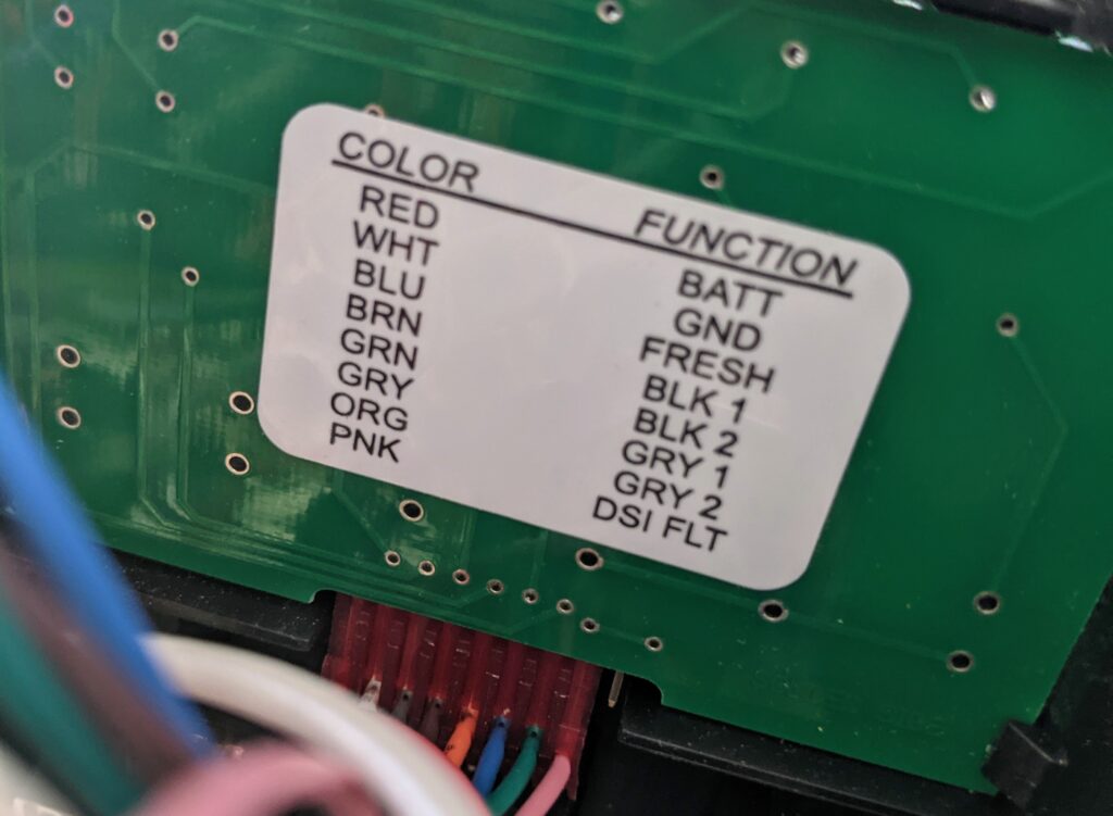
Wiring Diagram
The image below provides the wiring diagram that is out of the AGS manual. Also included is a chart to describe what each of the ports in our installation was connected to, to hopefully make your life easier.
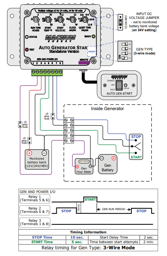
WARNING: Before utilizing the diagram or table below. Be sure to confirm the polarity and voltage of your wires, using a multimeter. Failure to comply may cause electric shock.
| I/O Port | Purpose | Source | Source Color | Connection | |
| 1 | Not Used | – | – | – | |
| 2 | 12v+ | Hour Meter (Onan Panel) | Red | Crimp Connection (fused) | |
| 3 | 12v+ | Convenience Center Panel | Red | Wago Connector Slot (fused) | |
| 4 | GND | Convenience Center Panel | White | Wago Connector Slot | |
| 5 | Start Switch | Cummins Onan Panel | Red | Crimp Connection | |
| 6 | GND | Cummins Onan Panel | Brown | Crimp Connection | |
| 7 | Stop Switch | Cummins Onan Panel | Blue | Crimp Connection | |
| 8 | Not Used | – | – | – |
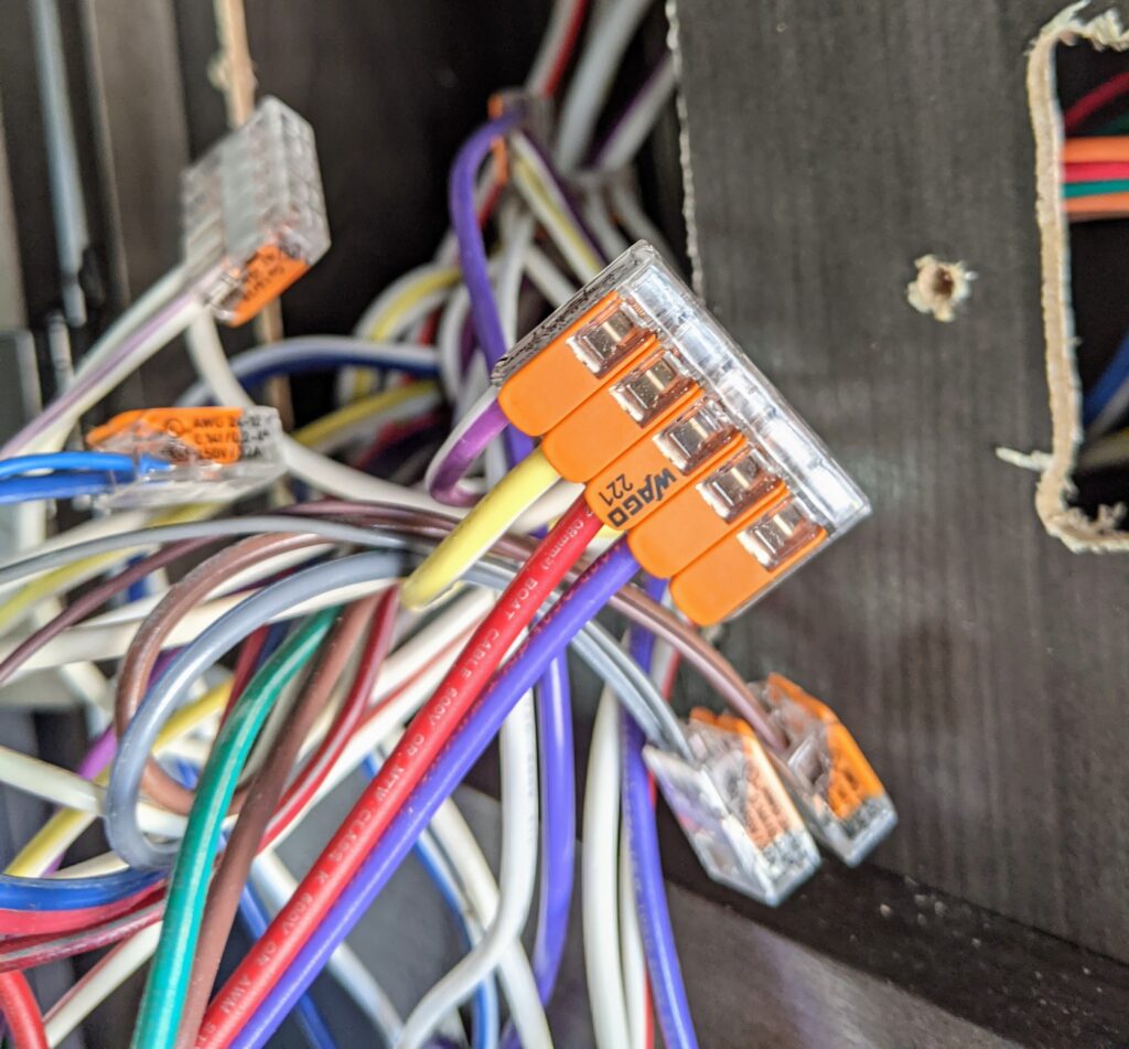
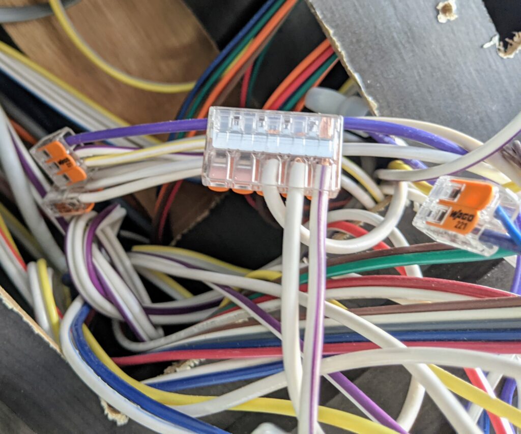
Connections to Convenience Center Panel
- I used Closed End Crimp Connectors to tap in to the appropriate power wires IAW the diagram above
- There are empty slots on the “Wago” connectors to tap in to the 12V+ and Ground wires. This means no splicing required. Simply lift up on the orange lever, insert wire, and close the orange lever back down
- I did use 5a inline Fuses on the 12V+ connections (as indicated in the chart above)
Reference
Included below are some images that might help clarify some of the instructions above.